The ten steps in the Life cycle of a Photovoltaic Panel
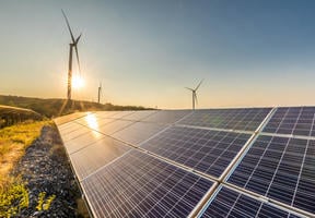
Photovoltaic cells convert sunlight into , but their production and use also have environmental impacts. This infographic walks you through the 10 key stages in the life of a - from quartz extraction to end-of-life . Using a method called , aligned with international standards, we can measure the environmental effects of each stage: energy consumption, CO₂ emissions, transportation and more. The panel studied is manufactured in China and used in France, allowing us to reflect the realities of the European market. The goal? To identify where the main environmental impacts occur and how to reduce them for more responsible solar energy.
The ten steps in the Life cycle of a Photovoltaic Panel
Methodology 


Step 1 - From Quartz to Silicon
Objectives 
- Obtain silicon from the silica (SiO2) present in quartz or sand
- Extract the oxygen from the silica to obtain metallurgical grade silicon (MG-Si)
Processes 
- Heat a mixture of quartz and carbon-based fuel (coke, coal and wood)
- Carbon and oxygen combine to produce CO2
- This leaves 98-99% pure metallurgical silicon
Impacts 
- Energy and water consumption, and CO2 emissions
Inputs
To produce 1 kg of MG-Si
 0.51 Water
(m3) 11 Electricity supplying the furnaces (kWh)
 23.10 Heat (MJ)
 3 Sand (kg)
 2.6 Fuel (kg)
N.B.: one kWh equals 3.6 megajoules (MJ)
Outputs
 29.5 Emissions of CO2 equivalent per watt (g)
  Fine dust

Step 2 - Toward Solar-Grade Silicon
Objectives
- Purify metallurgical silicon to obtain 99.9999% pure polycrystalline solar-grade silicon (SoG-Si).
Processes
- Chemical or metallurgical
- Mainly chemical at present, as this process produces a purer material, but consumes more energy and has inherent risks owing to the use of chlorinated products
Impacts
- These first two steps combined represent 40% of the energy consumed in the entire production cycle of a photovoltaic panel
Inputs
To produce 1 kg of SoG-Si
 0.35 Water
(m3) 49 Electricity
(kWh) 28.80 Heat (MJ)
 1.13 MG-Si (kg)
 2 Chemicals (kg)
Outputs
 88.1 Emissions of CO2 equivalent per watt (g)
  Chlorinated products

Step 3 - Silicon Ingot
Objectives
- Transform polycrystalline solar-grade silicon, whose atoms are randomly distributed, into monocrystalline silicon, where they are organized and aligned
- Shape silicon into ingot
Processes
- Melt down and gradually resolidify the solar-grade silicon by adding boron, a doping element
Impacts
- High gas consumption
Inputs
To produce a single 1 kg ingot
 5.09 Water
(en m3) including 4.8 m3 to be retreated 32 Electricity
(kWh) 68.20 Natural gas for the burner (MJ)
 1.02 SoG-Si (kg)
Outputs
 29,5 Emissions CO2 equivalent per watt (g)

Step 4 - Slicing wafers
Objectives
- Slice the monocrystalline ingots into thin slices - wafers - 250 micrometers (μm) thick
Processes
- Use a wire saw with an abrasive solution (slurry)
Impacts
- Significant loss of 30-40% of the material when sawing
- Potential for recycling the powder in other industrial sectors
Inputs
To produce 1 m2 of wafers
 0.056 Water
(en m3) 4.76 Electricity
(kWh) 4 Natural gas for the burner (MJ)
Outputs
 8,19 Emissions CO2 equivalent per watt (g)
  Silicon powder, slurry

Step 5 - Cell Production
Objectives
- Manufacture cells that convert light energy into electrical energy
- The cells can be square or rectangular (15-20 cm)
Processes
- Doping silicon exposed to a gas cloud containing phosphorous
- Deposition of a thin layer of aluminum
- Engraving of electric contact wires (aluminum and silver)
- Anti-reflection films and treatments in acid or alkaline baths
Impacts
- Use of electric furnaces and many irritant, corrosive and toxic chemical compounds
Inputs
To produce 1 m2 of cells
 0.17 Water
(m3) 17.7 Electricity
(kWh) 1.86 Various chemical elements (kg)
Outputs
 73.6 Emissions CO2 equivalent per watt (g)

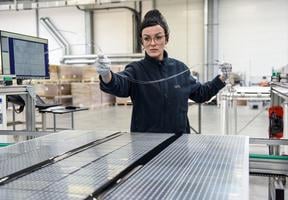
Step 6 - Module assembly
Objectives
- Protect the cells from the outside environment by assembling them in modules of 60 to 72 cells (1.7 m x 1m, surface area: 1.7 m2)
Processes
- Connect the cells
- Encapsulation in an Ethylene-Vinyl Acetate (EVA), envelope which, once heated, forms a layer of glue around the cells
- Protection using a solar glass pane and a rigid plastic sheet (backsheet)
- Fitting of an aluminum frame
- Addition of a junction box, wiring, and an inverter (to convert direct current into alternating current)
Impacts
- Handling of numerous chemical compounds that require the implementation of safety and discharge prevention measures
- The production of aluminum uses a lot of energy, and the process emits sulfur hexafluoride (SF6), a greenhouse gas with a high global warming potential (GWP)
Inputs
To produce 1 m2 of modules
 0.005 Water
(m3) 14 Electricity
(kWh) 17.62 Solar glass (kg)
 2.13 Aluminium (kg)
Outputs
 226 Emissions CO2 equivalent per watt (g)

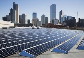
Step 7 - Installation
Objectives
- Panel transport, site preparation and installation on the ground
Processes
- Transport by sea/road, installation of structures for the solar farm
Impacts
- Carbon footprint of transport
- Forest clearing
- Loss of animal habitats
- Social acceptability of large facilities
Inputs
- Lifting and handling, civil engineering and construction materials

Outputs
 606 Emissions CO2 equivalent per watt (g)

Step 8 - Electricity Generation
Objectives
- Ensure auto-consumption or export of generated electricity into the grid
- Average lifetime of a solar panel: 30 years
Processes
- Suitable electric connections
- Maintenance of facilities
Impacts
- Impacts under the panels in the case of agrivoltaics: reduces light exposure but improves water retention
- Incidence on the panels: heat island effect
- Disrupts the movement of large mammals
Inputs
- Consumes very little energy (except for maintenance)
Outputs
- No CO2 emissions

Step 9 - Panel Recovery
Objectives
- Recover panels at the end of their useful life and take them to collection points
Processes
- Disassembly and transport by truck, optimizing journey times as much as possible
Impacts
- Risk of a high number of truck journeys generating a carbon footprint
Outputs
Emissions of CO2 equivalent par watt for the last two steps 9 and 10:
- Collection and recycling of used panels
-
 382 Emissions CO2 equivalent per watt (g)
-
- Recovery of 94% of the materials means that emissions estimated at -124 gCO2eq/W can be deducted from the final energy balance

Step 10 - Recycling
Objectives
- Separate the fractions a panel comprises: 68% glass, 12% aluminum, 9% plastic, 4% silicon, 1% tinned copper (tin-plated), 1% copper, 6% scrap material
- In total: 94% of a panel can be recycled and reused
Processes
- Separation of junction boxes, wiring and the aluminum frame to be melted down in a foundry
- Grinding: the recovered particles are sorted by air-separation (an air jet separates the glass, copper and fine particles), floating (plastics, traces of silver), eddy current (tinned copper, aluminum residues)
- Delamination: separation of the glass plate and photovoltaic cells using a hot knife (300°C)
Impacts
- Consumption of electricity and gas for machines and furnaces
- Scrap materials
Inputs
-
 Electricity (kWh)
 -
 Chemicals (kg)
The quantities of electricity and chemical products are not specified, as they vary greatly and account for only 6% of the panel’s total composition.
Outputs
Emissions of CO2 equivalent per watt for the last two steps 9 and 10:
- Collection and recycling of used panels
- 382 Emissions CO2 equivalent per watt
-
- Recovery of 94% of the materials means that emissions estimated at -124 g CO2eq/W can be deducted from the final energy balance
Based on the equivalent emissions assessed at each stage, calculate the total .
The stage-specific figures are given in g CO2eq per of capacity. However, according to industry standards, the total footprint should be expressed in g CO2eq per kilowatt-hour (g CO2eq/kWh). Assume that a photovoltaic system with a capacity of 1 kW produces an average of 1,000 kWh per year and has a lifespan of 30 years.
What is the carbon footprint of a photovoltaic system operated in France?
By summing up all the figures provided for each stage, we obtain the result:
1316 g CO2eq/W
(29.5 + 88.1 + 26.5 + 8.19 + 73.6 + 226 + 606 + 382 – 124)
A 1 kW photovoltaic system in France produces on average between 900 and 1,200 kWh per year, depending on the region and product efficiency. Using the intermediate value of 1,000 kWh, it will generate 30,000 kWh over an average lifespan of 30 years.
The system manufacturing emitted 1316 g for a capacity of 1 W, which amounts to 1,316,000 g for a capacity of 1 kW.
To express this per kWh, divide the emissions by 30,000 = 43.87, rounded to 43.9 g CO2eq/kWh.
This matches the standard value mentioned in the carbon footprint assessment: 43.9 g CO2eq/kWh.
This result aligns with the standard value published by ADEME. According to ADEME, the carbon footprint of photovoltaic systems is 43.9 g CO2eq/kWh for Chinese panels manufactured using the Chinese . For a European electricity mix, the footprint drops to 32.3 g CO2eq/kWh, and to 25.2 g CO2eq/kWh for a French electricity mix.
 This may interest you
See all